Optical SETI Photo Gallery -- Volume II
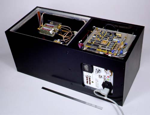
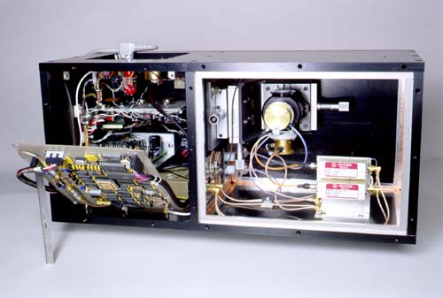
Completed Instrument -- Overall View
Here is the finished optical SETI instrument, housed in its compartmented
thick-walled (1/2") black anodized aluminum enclosure.  That's a 12" ruler;
the box measures 10"x10"x22".  The compartment on the right holds the
electronics, while the optics and detectors live in the compartment on the
left.  You can see the control panel at lower right.  This box is really
rugged, and weighs about 50 pounds; it bolts onto the echelle spectrograph
at the Cassegrain focus of the 61" telescope, with the light entering up
through the bottom into the optics compartment.  For this portrait the
covers have been removed; they bolt on to the top, in two sections, with
shielding gaskets to keep interference out.
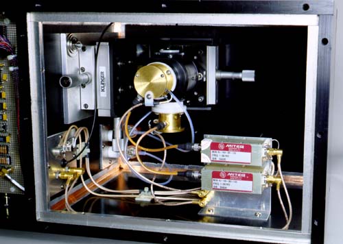
Optics Compartment
Looking into the optics compartment, we see the beamsplitter assembly, with
its pair of avalanche photodetectors, mounted on the 3-axis mechanical
stage that is used for initial alignment; light from the telescope enters
from beneath the stage.  An optical fiber enters the third beamsplitter
port, and is used to inject test flashes (under computer control) into both
detectors to verify operation before each run.  The preamps, copper shielding
tape, and cabling complete the artistic design and color scheme.
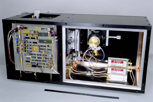
Top View (I)
Here we are looking into the instrument, with a good view of the optics and
circuit board.  You can see the signals and power wiring entering the
circuit, and you can spot the LED test flasher with its slender black fiber
near the bottom of the board.
Top View (II)
The circuit board is hinged, so you can get inside; in fact, every part of
the instrument comes apart easily -- this is an experiment, and we have to
be able to fool around with it as we learn what's out there!  In this
picture the circuit board is propped up by a 6" ruler, and you can see the
two low voltage power supplies (aluminum color) and also the high voltage
supply (gold color, near bottom of electronics compartment).  You can also
see some of the panel wiring, shown in more detail below.
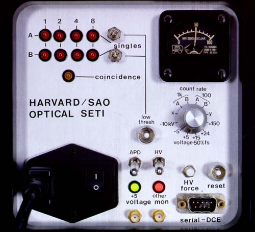
Control Panel
We're a little crazy in our lab about building pretty instruments, so we
tend to spend too much time making handsome panel layouts.  Of course, when
the instrument is all closed up and working, that's all you see!  Here you
see the indicators showing light flashes and coincidences, and the
multipurpose meter that monitors voltages and count rates.  AC power comes
in at lower left, and all the control and data goes to the computer via the
serial port at lower right.  The two colored lights at bottom indicate that
all power supplies are within normal limits (green), or not (red); the red
light here is telling us that the +24 volt supply is off -- that's because
the instrument has a little photodetector that looks around the room and
shuts off the high voltage (via the +24V) if it isn't dark; we do this to
protect the delicate (and expensive) photodetectors.  If you must operate
the thing with some room light, you do it by holding the button called "HV
force".
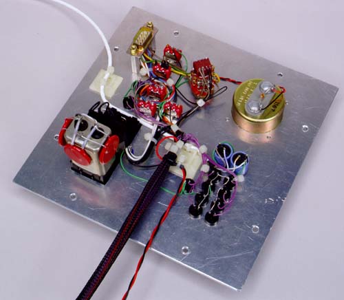
Panel Wiring
We're compulsively neat even about wiring you can't see!  Here's the backside
of the control panel, with its shipshape wiring all neatly gathered into
orderly rows, with lots of nylon cable wraps.  The white square thingies*
are handy to secure wiring down to flat surfaces; otherwise circuitry like
this can look just awful (for example, the thick custom cable at bottom has
26 wires in it, and they all go somewhere on this panel).  (* our
astronomer colleague Mike Davis calls these things "Mayan Temples", because
that's what they look like, scaled down in volume about a billionfold.)
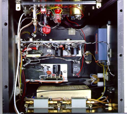
Electronics Compartment
Here's what you see if you remove the circuit board and look down into the
electronics compartment.  At the bottom of the picture you see the power
splitters that let us look at the raw signals if we need to; right above
them you see the brass colored high voltage power supply for the detectors,
and above that you see the two low voltage supplies.  The little black
rectangle to the right is a solid-state relay, which kills the high voltage
if there's light in the telescope dome; the even littler black square is
an electronic "crowbar" (honest, that's what it's called!), which shorts
out the power supply if the voltage goes above safe values.  The blue box
is the avalanche power supply.  At top you see the multicolored goodies
that comprise the control panel.