Optical SETI Photo Gallery
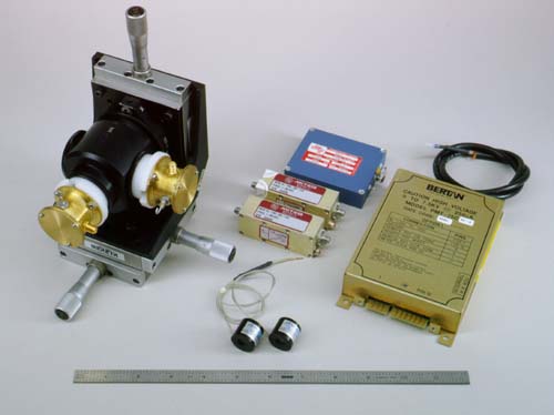
Optical Detector Assembly -- Exploded View
This is the business end of the experiment: the pair of fast
photo-detectors (bottom center) are held in the brass and nylon mounts
attached to the beamsplitter cube in the 3-axis stage at left.  The
"front-end" electronics is simple: a pair of fast low-noise amplifiers
(middle), and two power supplies (7.5 kilovolts and 150 volts).  The whole
business would fit in a shoebox.
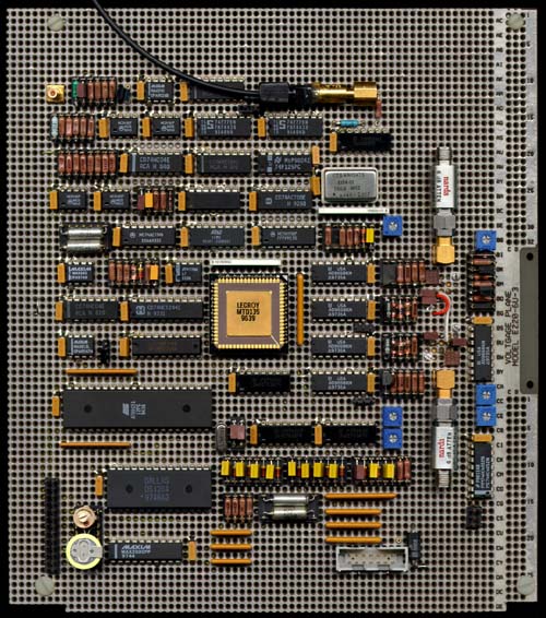
Electronic Circuitry
Here is the complete electronics "backend" -- the circuitry that takes
pulses from the pair of detectors and looks for coincident large pulses.
The input signals arrive at the two gold connectors at right.  The large
black chip at lower left is a micro-controller, a single-chip computer that
oversees what's going on and reports it to the remote PC; it's the brains
of the circuit.  The handsome golden chip at center is the brawn -- an
8-channel, 16-event/channel, high-speed (500 picosecond) "time-tagging" IC
from LeCroy.  At the bottom left is a calendar clock -- we want to know
when anything interesting happens.  At the top right is the optical pulser,
used to inject test flashes to verify system operation.
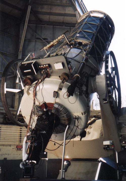
The 61" Telescope at Harvard/Smithsonian
This is a portrait of the Oak Ridge Observatory 61" reflecting telescope.
It was built in 1933, and it is the largest optical telescope east of
Texas.  Come visit!
Schematic Diagram of OSETI Electronics
Only a technoid could love this picture -- a schematic diagram of the
optical SETI electronics (well, part of it, anyway).  But you don't have to
love it to know that it is critical to the whole experiment.  If you know
electronics, you can probably figure out what's going on.  For the
uninitiated it is probably enough to know that signals sort of go the way
the little circuit symbols seem to point; and they do good things when they
get there.
and here's the next part of the same circuit....

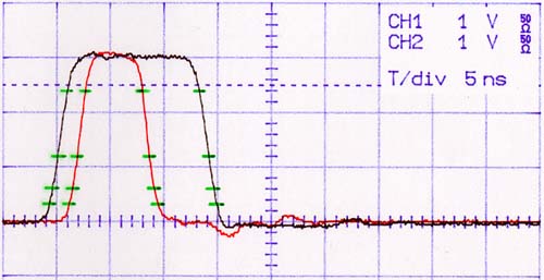
Test Pulses -- Mimicing The Real Thing
Here's an example of a pair of pretty fast test pulses (the red and black
traces), shown on an oscilloscope: time goes to the right (5 nanoseconds --
billionths of a second -- per big division) and voltage goes up (1 volt per
big division).  The circuit reports the time at which each signal passes
through the green lines shown.  The times it reported are exactly in
agreement with the times you measure on this 'scope trace.
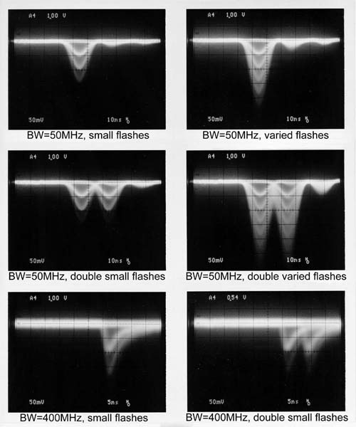
Detector's Response to Test Flashes
Here are oscilloscope photographs showing what the detector reports when
you send very short flashes of light in its direction.  As always, time
goes to the right, and voltage goes up.  The downward "bumps" are the
output from flashes, negative electrical pulses about 10 nanoseconds long
(that's 1/100,000,000 of a second).  What's really important is that the
detectors clearly show when they see one photon, two photons, three
photons, etc -- as successively deeper bumps.  This is called "pulse height
resolution," and in this regard these detectors are extraordinary.  We care
about that because we want to reject starlight (random single photons),
while detecting (with excitement) an incoming laser flash that delivers
several photons at once.  These photos also show that two flashes can come
very close together and be properly reported.  In the upper four photos the
detector's native speed has been tamed with an electrical filter; in the
bottom pair it can show off its blazing speed (about 5 nanoseconds, pretty
fast).