Assembly Photos
Figure 1
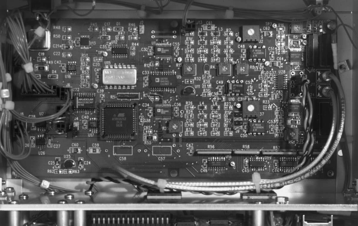
Here is the interior of the synthesizer seen from above. Note the SMB connections to
the sine wave outputs, the twisted pair connections to the sync outputs, and AMP-MODU
connections to PCB headers.
Figure 2
A view of the pushbutton matrix, LCD, and 3-terminal strip (power, ground, pwr sense).
Note the 4 resistors on the pushbutton matrix board (in series with row address
lines). Also note the 4 ohm power resistor to the right of the LCD; this power
resistor provides the correct LCD backlight current. The potentiometer visible above
the LCD provides contrast control; its wiper is tied to the LCD VEE line, while +5
and ground attach to the other pot leads.
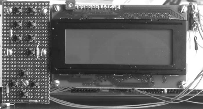
Figure 3
The LCD and pushbutton matrix are attached to an aluminum plate to correctly position them
with respect to the front panel. The plate is attached to the side panels of the
enclosure using the right-angle brackets seen here. The use of 3 brackets per side
is just a little excessive.
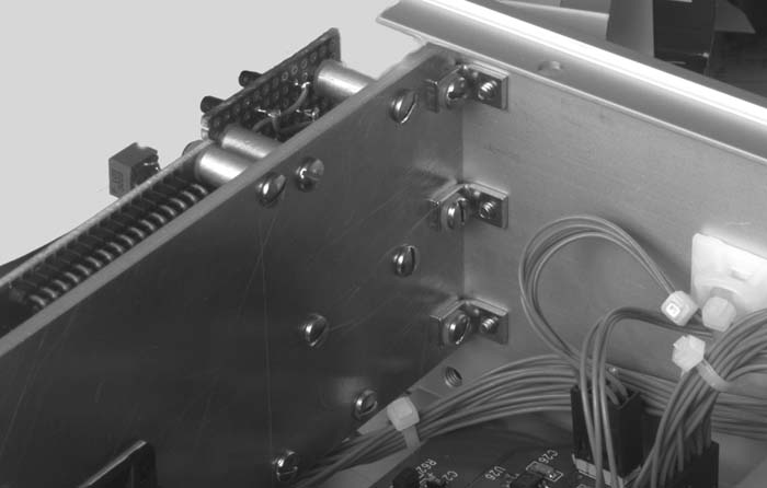
Figure 4
These are the metal spacers used to position correctly the LCD and pushbutton matrix with
respect to the front panel. Note the use of nylon spacers to keep the metal machine
screws from touching pads on the LCD printed circuit board.
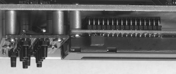
Figure 5
A closeup of the 3-position strip (+5, ground, and power sense). Note the 1k pullup
resistor, the 4 ohm power resistor that biases the LCD backlight, and the large tantalum
capacitor that bypasses the +5 supply. This capacitor is necessary for proper
operation; otherwise, large spikes can appear on the power line as the LCD backlight is
switched on or off.
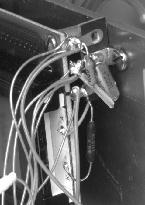
Figure 6
The reference select circuit consists of a 3-position (on-on-on) switch, a BNC connector
as an external reference input, and a 50 ohm termination resistor. From this angle,
the termination resistor is just barely visible to the left of the body of the switch (see
below for closeup). The reference circuit connects to the PCB via the 3x2 AMP-MODU
header seen in the lower left corner.
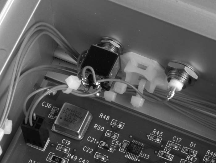
Figure 7
Closeup of the 50 ohm termination resistor that is part of the external reference circuit.
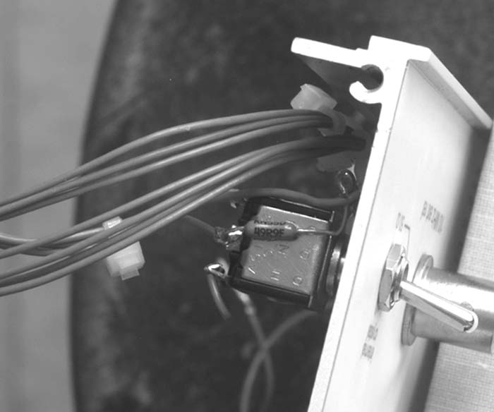
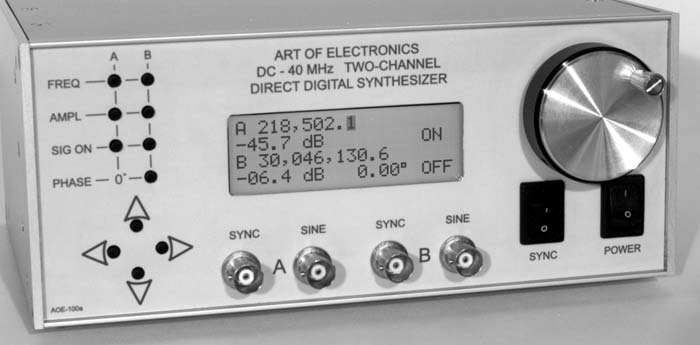
Figure 9
The inside of the front panel. The two rocker switches are in the lower left below
the rotary encoder; the SPDT is the power switch, and the DPDT is the sync switch. The
related 3x2 AMP-MODU connector attaches to the PCB at J13. The rotary encoder
nominally has a 5-pin straight header. Here, that header has been replaced by a
5-pin right-angle header due to space constraints. A 5x1 AMP-MODU should be used to
connect to the rotary encoder.
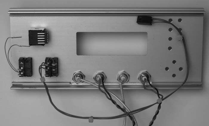
Figure 10
The outside of the back panel.
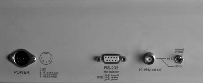
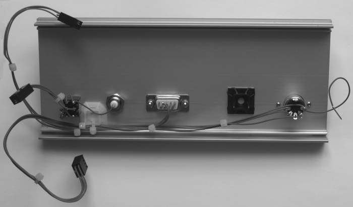
Figure 11
The inside of the back panel. There are 3 AMP-MODU connector cables (from the top:
RS-232 [J6], reference select [J3], and power [J8]). The wire with pin
connector to the right of the DIN is a +5 connection which provides power to components
(LCD, rotary encoder) on the front panel.